Numeric analysis of nose cone heating: first steps

Calvin and Hobbes on engineering design

Calvin and Hobbes on engineering design

The most accurate way to find the aerodynamic heating on a high velocity flight structure is to fly it and measure what happens. This approach can be expensive, though, requiring building more and more robust rockets until finally one isn’t destroyed. Crazy as it may sound, it is an approach that I’ve seen used.

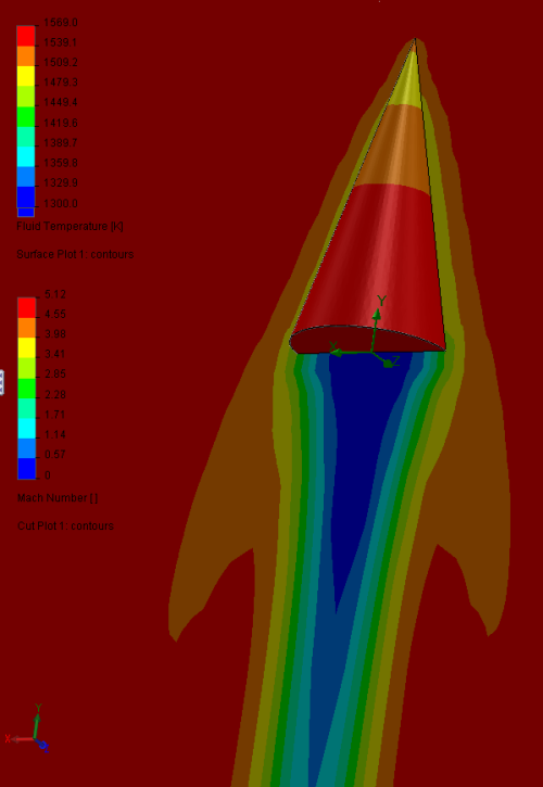
Another approach is to model the rocket in Computational Fluid Dynamics (CFD) software. This works well for steady state processes, but is incredibly processor-intensive for a time-dependent process such as trying to find the total heating of a nose cone in a flight trajectory with continuously changing air velocity, pressure, and temperature. A steady state analysis can be done with high fidelity results in under an hour, but a 40 second flight simulation requires about a month of processor time.

Least accurate, but easiest, is using empirical models. Rockets and planes have been flown supersonic many times, and from that dataset researchers have created simple equations that can crudely predict the temperature and heating that will be seen in flight.

Recovery temperature

In a previous post I showed the stagnation temperature for a set of flight conditions. Stagnation temperature is the highest temperature of the gas possible, converting all of its kinetic energy into heat.

A more accurate baseline number is the “recovery temperature”, which is related to stagnation temperature but reflects the fact that the conversion to heat from dynamic pressure isn’t total. From Tactical Missile Design, by Eugene L. Fleeman:

TRecovery = TFree Stream ( 1 + 0.2 r M2 )

Where:

  • TRecovery is the recovery temperature, in Kelvin or Rankine.
  • TFree Stream is the free stream temperature; for the nose cone it’s the ambient air temperature at the given altitude, in Kelvin or Rankine.
  • r is the recovery factor. For stagnation r = 1; turbulent boundary layer r = 0.9; Laminar boundary layer r = 0.8. We’re in the turbulent regime for our analysis.
  • M is the mach number.

Adding that to the spreadsheet used previously:

Altitude (m) Temp (K) Pressure (Pa) Density (kg/m^3) Dynamic press (Pa) Mach number Stagn. temp (K) Recovery temp (K)
827 282.8 91777 1.131 66898 1.02 341.7 335.8
2022 275.0 79278 1.004 142116 1.60 415.9 401.8
8056 235.8 35312 0.522 33808 1.17 300.3 293.8
9955 223.4 26619 0.415 126247 2.60 526.2 495.9
11750 216.7 20108 0.323 199903 3.77 831.9 770.4
13703 216.7 14771 0.238 247967 4.90 1255.6 1151.7

As you can see, the recovery temperature is a bit lower than the stagnation temperature, but not hugely. It’s still seeing very hot air when it’s flying at Mach 4.9 at 13.7km.

Heat flux

Tactical Missile Design also provides a very imperial empirical equation for calculating the heat flux the nose cone will see.

Q = 345 ρ0.8 M2.8/x0.2

Where:

  • Q is the heat flux in BTU per square foot per second.
  • ρ is the free stream air density, in slug per cubic foot.
  • M is the mach number.
  • x is the distance from the tip, in feet.

With this equation we get the following chart for the heating of the nose at various positions at the high velocity data point:

Calculation of heat flux

400 BTU/ft^2/s is 4.5 megajoules/m^2/s. It’s a lot of heating. Rounding the tip significantly reduces the heating and causes a minimal increase in drag coefficient.

Converting to temperature rise

As before, we need material properties and part dimensions to convert the heating rate into a peak flight temperature of the part. We will tackle that in a subsequent post.

What of Sugar Shot?

Ultimately we’re trying to establish what materials will be needed for this theoretical Sugar Shot rocket and its very high flight speeds low in the atmosphere. Fleeman has this to say about that:

Figure 4.14

Examples of uninsulated structure materials that are cost effective for the short duration flight of tactical missiles are shown in Fig. 4.14. An assumption is that the heat conducted to the airframe is large compared to the heat radiated by the airframe. This assumption is most applicable at low altitude/high atmospheric density. The airframe temperature would be lower at high altitude, due to the relative importance of radiation from the airframe. The example airframe materials selected for the figure are based on the consideration of weight, cost, and maximum temperature capability. Composite materials are a new technology that will find increased use in new missile airframe structure. High temperature composites have particular benefits for hypersonic missiles, providing weight reduction. Titanium alloy technology also enables lighter weight missiles in a hypersonic, high temperature flight environment.

As shown in the figure, at subsonic and low supersonic Mach number, graphite/ epoxy and aluminum or aluminum alloys are attractive choices for a lighter weight structure without external insulation. Graphite/epoxy and aluminum alloys have high strength-to-weight ratio, are easily fabricated, have good corrosion resistance, and are low cost. For higher Mach number, graphite/polyimide composite structure has an advantage of high structure efficiency at higher temperature for Mach numbers to about Mach 4. For flight to about Mach 4.5 without external insulation, titanium structure and its alloys are preferred. A disadvantage of a titanium structure is higher material and machining cost. For example, a titanium part has a material cost that is up to 18 times that of aluminum and a machining cost that is up to 13 times that of aluminum. However, the cost to cast a part made of titanium is comparable to the cost to cast an aluminum part. Small tolerance (e.g., +/−0.001 in.) is required to avoid expensive touchup machining. Up to Mach 5.7 without external insulation (about 2000◦F), super nickel alloys such as Inconel, Rene, Hastelloy, and Haynes must be used. Precision casting should be used to minimize the expensive machining and material cost associated with super alloys. Above Mach 5.7 the super alloys require either external insulation or active cooling. Active cooling is usually not cost effective for tactical missiles.

This suggests that if a rocket is built with the performance expected, the nose cone may need to be a short blunted Inconel tip attached to a high temperature composite nose cone using state-of-the-art materials. Or it could be a lower temperature composite nose cone covered with an ablative material.

Hypersonics are not a project for fiberglass and epoxy.

Addendum to nose cone heating: stagnation temperature

It’s useful to calculate the stagnation temperature of the air. It gives an upper bound to the temperature that the nose could reach.

Altitude (m) Velocity (m/s) Temp (K) Pressure (Pa) Mach number Stagnation temp (K)
827 344 282.8 91777 1.02 341.7
2022 532 275.0 79278 1.60 415.9
8056 360 235.8 35312 1.17 300.3
9955 780 223.4 26619 2.60 526.2
11750 1112 216.7 20108 3.77 831.9
13703 1445 216.7 14771 4.90 1255.6

Going near Mach 5 at 13km: quite toasty.

Solidworks Simulation of near hypersonic nose cone

Richard asked if I could do some simulation of the nose cone heating of the Double Sugar Shot rocket. It’s quite a big nose cone, nearly a meter long by 169mm diameter (~3ft by 6.65″). I modeled it in Solidworks, then ran it in Solidworks Simulation. With my current computer, it takes a few days for it to complete a run, then a few days more to get time to check the results and re-run it if anything was off. Following is the final results of one run.

I was given a few points with altitude, velocity, temperature, pressure, and density. I calculated dynamic pressure.

Altitude (m) Velocity (m/s) Temp (K) Pressure (Pa) Density (kg/m^3) Dynamic pressure (Pa) Mach number
827 344 282.8 91777 1.131 66898 1.02
2022 532 275.0 79278 1.004 142116 1.60
8056 360 235.8 35312 0.522 33808 1.17
9955 780 223.4 26619 0.415 126247 2.60
11750 1112 216.7 20108 0.323 199903 3.77
13703 1445 216.7 14771 0.238 247967 4.90

The last point had the highest dynamic pressure (also known as “max Q”) for the data points given, so I ran it in the simulation as it may have the most interesting results. That point is 1445 m/s at 13703 m MSL. For the simulation input I used air as the fluid at the density at that altitude; 14771 Pa and 216.65 K. I set the surface roughness to 6.35 micrometer, which should be appropriate for a finish equivalent to smooth paint.

Here’s a video of one result, followed by charts of others. Click to embiggen.

The mesh:Image


Gas density:Image


Pressure:Image


Temperature:Image


Velocity:Image


The shockwave coming off the cone is prominent in all the plots, and raked back at a severe angle due to the high velocity. The temperature is relatively low, aside from a small warm area just downstream of the nose.

Here the analysis wasn’t set to deal with conduction in solids, so it’s impossible to give temperatures for the solid part, just for the gas touching the part. It does bound the maximum temperature the part could reach, which is a reasonable design point, but it isn’t as interesting as having a plot of the actual expected part temperatures.

To analyze the heat going into the nose cone its material properties must be defined. These include:

  • Density
  • Specific heat (possibly at multiple temperatures)
  • Conductivity type (Isotropic, Unidirectional, Asymmetrical/Biaxial, or Orthotropic)
  • Thermal conductivity (which can also vary with temp and can be multiple, if not isotropic)
  • Melting temperature (the glass transition temperature of the resin would be a good analog for a composite nose cone)

The thickness of the nose cone would also need to be known, especially if it varies at different positions.

For the next analysis I will shorten the length of the straight tube to just a few inches, close the end so that the flow inside isn’t taking calculation cycles, and possibly change the size of the bounding box to remove the volume downstream of the nose.

A full simulation can also be done with time dependent variables. The velocity, temperature, and pressure can all be varied with time to get an idea of the total heating over the flight. However that analysis would probably take weeks for the computer to run. It’d be interesting to try, though.

Image

Colorful fluid drawing of a cone traveling hypersonically

Colorful fluid drawing of a cone traveling hypersonically

Running an experiment with some very basic geometry to see the capabilities of Solidworks Flow Simulation in analyzing a shape traveling mach 5+.

The cone is 4 inches tall and 2 inches wide at the base, to roughly simulate the tip of a rocket nose cone at a severe Max-Q. Fluid is air at STP.

2013 Sparkfun Autonomous Vehicle Competition Recon

Paul Breed asked me to check out a couple things about the course for the 2013 Sparkfun AVC, so I went to check it out.

Here’s the ground course video:

The course generally slopes upward from the start line to the third corner, then slopes back down to the fourth corner.

There’s also a gallery of photos on Flickr. Here are a few of them:

IMG_6129.jpg
Location of potholes on the ground course.

Puddle depth action shot
Pothole depth.

Crack in the straight after turn one, there's a series of them
Size of the largest cracks. These will probably close up somewhat as it gets warmer.

Looking at the trees from the dock
Size of the trees over the aerial path. They’re forty or fifty feet tall.

I hope this helps any potential entrants.

Boilerplate midbulkead

After the previous work on the midbulkhead, I was told that the specifications I’d been working from had changed. So I dumped all that and designed a boilerplate version instead.

boilerplate bulkhead-Study 1-Results-Factor of Safety1.analysis

PDF of print. And yes, it now has four holes, but I haven’t renamed it. It’s made out of a 0.75″ plate of plain carbon steel, and weighs 5.11 lb, compared to 1.31 lb for the 7075/PMMA laminate proposed in the last post.

Rick Maschek asks, You say “I remain not a fan of this overall approach.” Reasons and or suggestions for something different?

There’s a saying that “An engineer is someone who can do for a dollar what any fool could do for two.” At this point we’ve definitely spent a metaphorical three dollars in time and effort on the midbulkhead concept. The best approach to it, since its function is just a check valve, would be to make a check valve. It’d be a bit more complex, but would be easily reusable and easy to test.

More generally, a two burn sugar motor is never going to go to space, the stated goal of the project. A two stage rocket is the way to go and is superior in almost every way. It would require relatively little R&D compared to the four dollars that’s been spent on the two burn concept so far.

If it turns out that it isn’t possible to build a sugar motor large enough to be a first stage for a two stage rocket due to the propellant’s physical characteristics, then it similarly wouldn’t have been possible to do a two burn rocket of the same size. Time spent trying to figure out the two burn architecture is time wasted until it’s been demonstrated that it’s possible to even get one burn of sufficient impulse.

Sandwich bulkhead thinned down

Regarding the latest design, Richard asks, “can the edges be modified to fit with the space shown in the attached sketch?”

richards question
(original PDF: MBH CSD interface detail)

Short answer: no. I reduced the thicknesses as low as I could go and still get reasonable factors of safety. It is thinner, but it’s still not half an inch thick at the edge.

three hole laminate
(as a PDF: three hole laminate)

Further, the retainer ring will have to be machined after a couple complete sandwiches have been made, to find out how thick the final part is including adhesive.

There’s also the question of how it’s sealed into the midbulkhead. I didn’t add an o-ring gland. I expect silicone would work, as long as the parts are kept at a relatively constant temperature.

I remain not a fan of this overall approach.

Three hole bulkhead: revision 2 of a stressed skin approach

Rev 2 of the stressed skin approach to the bulkhead. Holes are added to the PMMA disk, and covers are added over the holes. Each cover is 1.495″ in diameter, to fit through the 1.6″ diameter throat.

Material is changed to 7075-T6 for the aluminum parts to increase the FOS. Contours are simplified to make machining simpler. Top and bottom of sandwich are now identical parts.

FOS:
three hole laminate-Study 1-Results-Factor of Safety1.analysis

Displacement:
three hole laminate-Study 1-Results-Displacement1.analysis

Cross section view in midbulkhead:
three hole laminate in bulkhead

The holes through the PMMA are 1.3″ in diameter. This give a full area just under 4 square inches, compared to 2 square inches for the nozzle throat. This should ensure that there is no sonic lock in the flow as it goes through the delay disk. Having sonic flow into the aft chamber would result in a large increase in heat flux into the walls of the chamber, and should be avoided if at all possible.

Sandwich construction melting bulkhead

PMMA was shown to be the fastest to erode in engine tests, and is one of the weaker materials tested. My original mass-effective solutions to the problem were discarded when the midbulkhead was machined, so I started over with a stressed skin approach, similar to the concept of honecomb or foamcore composites, where faces of a part take tensile and compressive load while a weaker interior takes shear.

Here the faces are made of 2024-T3, though it could be a steel of similar strength. The upside of the aluminum is that it’s much lighter, the downside is that the firing will likely anneal it and require new parts.

The aluminum faces are bonded to a simple disk of PMMA. Ideally with a perfect layer of cyanoacrylate, as it bonds extremely well to PMMA, but a high strength epoxy would probably suffice as well and give more working time.

The parts assembled in the midbulkhead, the retainer and screws are omitted:
bulkehad in midbulkhead

The analysis of the sandwich with 1000psi on the bottom surface; displacement:
laminate sandwich-Study 1-Results-Displacement1.analysis

FOS:
laminate sandwich-Study 1-Results-Factor of Safety1.analysis

It could be bumped up to over 2 for the entire part by increasing the 2024 thickness beyond the current quarter inch. The coaxial groove on the top surface isn’t needed for a boilerplate motor, it is a weight optimization. The lower surface does need some thickness removed from near the edge so as to fit in the space provided in the as-machined part.

The port through the center is not shown for simplicity in simulation. A plurality of ports would reduce the odds of the destruction of the lower casing.

This approach is generally inelegant, and would be best replaced with a flapper or retained pop-off valve mechanism, which would eliminate the supersonic jet of gas into the lower casing that this concept is bound to create.

Richard’s chamber separator disk geometry, using polycarbonate, 20% glass filled

An analysis of a CSD based on geometry specified by Richard Nakka. In this run glass filled polycarbonate was used as the material, with the following properties:

Elastic modulus in X: 1200000 psi
Poisson’s Ration in XY: 0.37
Tensile Strength in X: 17100 psi
Compressive Strength in X: 18000 psi
Yield Strength: 17400 psi

Loaded from the bottom with 1000psi, displacement plot:

Loaded from the bottom with 1000psi, FOS plot:

Loaded from the top with 1000psi, displacement plot:

Loaded from the top with 1000psi, FOS plot:

In short, it is unsurprisingly better than the weaker delrin, but retains areas with factors of safety lower than desired.